Selecting the right fiber laser cutting machine is a crucial investment that directly impacts your productivity, efficiency, and long-term profitability. With numerous technical factors, compliance requirements, and operational considerations to navigate, making an informed choice can be challenging.
This comprehensive buyer’s guide to buying a fiber laser is designed to simplify your decision-making process by clearly outlining critical considerations—from choosing the appropriate laser power and understanding CNC control systems to evaluating safety standards and warranty terms.
Armed with expert insights, structured checklists, and practical recommendations, you’ll be well-equipped to choose a CNC fibre laser that precisely meets your business needs.
1. Introduction
2. Core Components & Technology
- Fibre Laser cutting head
- Laser Power – more is not always better
- Measuring distance from material
- Machine dynamics and cutting efficiency
- Cost of laser maintenance
3. Mechanical Design & Motion Control
- Frame design
- Ergonomic working
- Traditional CNC drives
- Vs Linear Drives
- Control Systems
- Hardware Vs Software Interpolator
4. Programming, Software & Automation
5. Buying the Right Machine
- Checklist: Rules to follow when purchasing a fibre laser
- Safety considerations
- Warranty and Installation Considerations
- Contract Specifications and Commissioning Considerations
6. Conclusion
1. Introduction
Fibre Laser Defintion
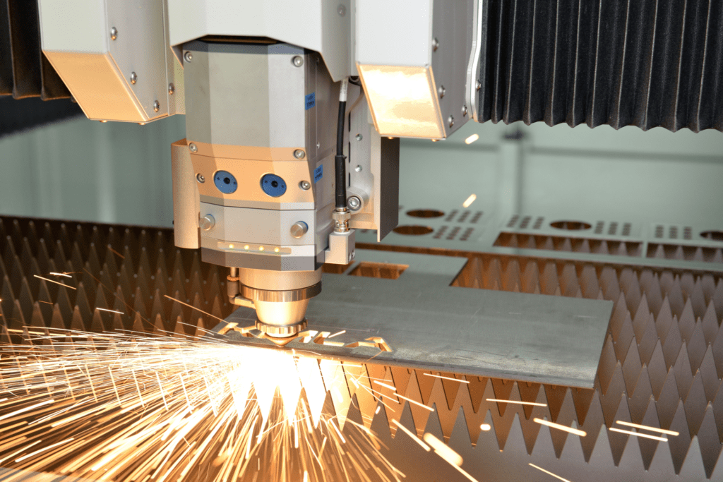
A fibre laser is a type of industrial cutting machine that uses an optical fibre as its active gain medium, producing an incredibly focused, high-powered beam of light capable of slicing through metal with extreme precision and speed. Unlike traditional CO₂ lasers, fibre lasers offer superior energy efficiency, lower maintenance requirements, and the ability to cut a wider range of materials — especially reflective metals like aluminium, copper, and brass.
At the heart of the system is a laser source that generates a beam of light, which is then amplified and delivered via fibre optics to a cutting head. The beam is focused to a fine point and directed onto the material surface, where its concentrated energy melts, burns, or vaporises the material with remarkable accuracy. Controlled by CNC (Computer Numerical Control) systems, fibre lasers can execute intricate cutting patterns across sheet metal with minimal human input.
CO2 to Fibre Laser Cutting
For many years CO2 lasers have dominated the sheet metal cutting industry. Despite high maintenance costs and their relatively low efficiency ratings, companies were still able to generate significant profits using this technology. As the number of manufacturers producing CO2 lasers increased, the price of the equipment decreased, but so did research leading to a stagnation in the technology. In 2010, we saw a change, and the fibre laser revolution began.

Fibre lasers offered significant advantages over CO2 with shorter wavelengths and increased cutting speeds. During the early years of fibre lasers, development was challenging with low-powered sources, head issues and legacy restrictions inherited from CO2 machines. This resulted in the first generation of fibre lasers being barely more efficient than traditional CO2 lasers.
A key benefit with fibre laser technology that users enjoy today is its ability to process thinner sheets at significantly higher speeds. Unfortunately, early fibre models relied on antiquated control systems that were just not capable of processing data quick enough to cut efficiently. The original CNC systems for CO2 lasers were single purpose, generic and largely designed for slower machine tool processing and just not capable of exploiting fibre laser technology.
Today, the industry giants manufacturing fibre lasers appear to be content to continue with this approach. The result? Despite new lasers being equipped with fibre sources reaching cutting speeds five times faster than CO2, real world processing efficiency sees little more than a 30% increase.
2. Core Components & Technology
Fibre Laser cutting head
The laser head is a critical component in any laser cutting system, significantly impacting cutting quality, piercing speed, and the range of material thicknesses that can be effectively processed. Initially, when fibre optic lasers entered the market, the compatible laser heads were relatively basic, lacking automated controls or integrated safety features.
Subsequent developments introduced automation and safety functionalities, initially limited to fibre lasers with power outputs up to 2kW. However, rapid advancements in laser technology quickly revealed the limitations of existing laser heads, turning them into potential weak points in higher-powered fibre laser systems.
Laser manufacturers faced considerable challenges when adapting heads to handle higher power levels, primarily due to the absence of standardized design practices. Early fibre laser heads provided no early warning mechanisms, meaning operators often remained unaware of issues until significant damage had occurred. One common problem involved overheating of the focusing lens, resulting in melting, evaporation, and subsequent damage to adjacent optical components, including the collimator lens and the fibre optic quartz tip. Such scenarios typically required the replacement of the entire optical system, as damage went unnoticed until extensive harm had occurred.
To address this issue, newer generations of laser heads included temperature sensors that monitored the lens casing. However, due to the lens glass’s low thermal conductivity, these measurements were delayed, frequently triggering protective shutdown mechanisms too late and failing to prevent lens damage.
In response, Kimla has developed an innovative contactless approach for directly measuring the lens surface temperature using micro-bolometric matrices. This technology provides instantaneous temperature monitoring precisely at the source, enabling immediate automatic shutdown if the lens temperature exceeds safe operating limits, effectively safeguarding the optical components and minimizing downtime.
Laser Power – more is not always better
Initially, fibre lasers used in metal cutting had power outputs measured in hundreds of watts, capable of cutting metal sheets up to approximately 3 mm thick at moderate speeds. Naturally, increasing the power output became essential to enhance cutting speed, efficiency, and the range of materials that could be processed. Technological advancements quickly brought lasers into the kilowatt power range; however, this increase in power did not translate directly into proportional improvements in cutting efficiency or maximum cuttable thickness.
Early fibre laser machines typically ranged between 1 kW and 2 kW, with the cutting capacity and thickness generally improving in proportion to increased power. However, as laser power exceeded 2 kW, the proportional relationship weakened, and further increases in power yielded diminishing returns in terms of cuttable thickness.
It’s important to emphasize that the maximum cutting thickness achievable does not always correlate directly with the laser’s power rating. Performance in controlled laboratory conditions differs significantly from real-world industrial applications. Consequently, when selecting a laser source, it is advisable to factor in a power reserve. This power reserve broadens the “process window”—the range of operational parameters under which cutting quality remains acceptable. Machines with limited power reserves present challenges in setting optimal cutting parameters, especially when handling lower-quality materials.

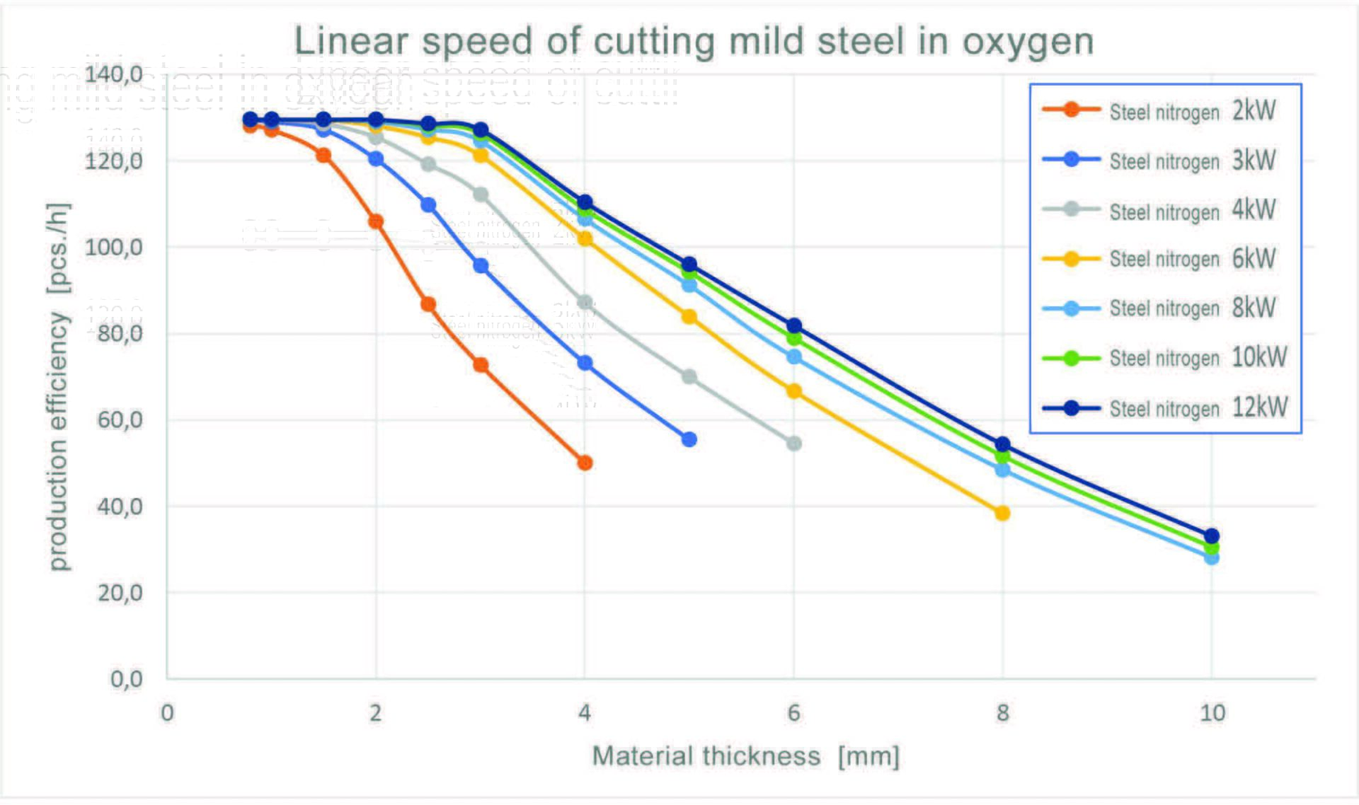
Cutting non-ferrous metals, stainless steel, aluminium, titanium, or thinner mild steel typically involves nitrogen, whereas thicker mild steel is generally cut using oxygen. Cutting with oxygen results in a wider kerf and slower speeds compared to nitrogen. Thus, using nitrogen for cutting mild steel, when sufficient laser power is available, can significantly enhance efficiency and reduce operating costs.
As illustrated by the data, cutting thinner sheets with nitrogen offers substantial benefits, achieving cutting speeds up to five times faster compared to oxygen at the same laser power. This advantage reduces somewhat with thicker materials but remains significant. Although nitrogen cutting consumes gas at higher pressures, the overall cost is offset by nitrogen’s lower price and greater efficiency.
The data also highlights the correlation between laser power and maximum achievable cutting thickness. For instance, a 3 kW laser can cut mild steel sheets up to 15 mm thick, but its nitrogen cutting capability is limited to around 4 mm. Doubling the power to 6 kW extends the nitrogen cutting capability to 6 mm, enabling cutting speeds approximately six times faster than a 3 kW laser.
These examples clearly demonstrate that investing in higher-power lasers offers considerable economic and operational advantages. However, selecting the appropriate laser power should always involve evaluating the efficiency of the entire cutting process.
Measuring distance from material
Accurate measurement is vital for laser cutting efficiency. The laser head must precisely follow uneven material surfaces at high speeds. Traditional laser heads measure nozzle-to-material distance at a frequency of around 1 kHz (1,000 times per second). While adequate for slower speeds, this frequency becomes insufficient at higher speeds, potentially risking collisions. Kimla addressed this by introducing advanced measurement units with DSP processors, increasing measurement and height correction frequency to 20 kHz for rapid, precise adjustments.
A crucial aspect of measurement involves piercing thicker materials. During piercing, escaping sparks and molten material can damage safety windows. Typically, lasers pierce at a maximum height of 10 mm, limiting effectiveness and causing faster wear. Kimla systems extend measurement ranges up to 20 mm, significantly improving piercing effectiveness and optics longevity.
Kimla’s laser heads also feature automatic focal height adjustment, ensuring optimal piercing conditions even from significant distances. Additionally, maintaining a secure and controlled environment within the laser head is essential. Kimla lasers feature a number of sensors monitoring key parameters, including:
- Temperature of the top safety window
- Temperature of the collimator lens itself
- Temperature of the collimator lens housing
- Temperature of the Focusing lens itself
- Temperature of the Focusing lens housing
- Temperature of the safety window
- Temperature of the housing
- Temperature of the head height controller
- Presser at the nozzle
- Pressure in lens compartment
- Humidity in lens chamber
- Total loss power at the head
- Total loss power at the fibre optics connection
- Beam reflection from the material
Operators regularly replace safety windows, a straightforward yet sensitive task. Common mistakes include leaving window compartments exposed, using damaged windows, or improperly sealing windows. Kimla’s design incorporates an additional protective safety window, reducing the risk of serious optic damage and ensuring secure, efficient maintenance.
Machine dynamics and cutting efficiency
Machine dynamics significantly influence cutting efficiency, determining how feeding speed adjusts based on the contours a machine follows. Dynamics encompass speed, acceleration, and pick-up rates. While cutting speed is limited primarily by the type and thickness of metal sheets, laser power, focal length and height, gas pressure, nozzle diameter, and distance, head movement speed depends mainly on path shape, linear acceleration, and the centrifugal forces experienced during curves.
Acceleration, or the time required for a machine to reach its designated speed, often requires limitation at curves to ensure that combined linear and centrifugal forces do not exceed the drive system’s capabilities. Pick-up, representing the rate of change in acceleration, must be carefully balanced; insufficient pick-up can cause sudden jerks, whereas excessive restriction prevents machines from achieving their target speed, significantly reducing efficiency.
Acceleration is particularly critical for cutting thin metal sheets, where laser power allows high cutting speeds that might be unattainable due to short cutting distances. In cases involving intricate details, actual cutting speeds achieved may only be a fraction of the potential maximum. Consequently, machine dynamics, rather than laser power alone, often determine overall efficiency when cutting thinner sheets. This becomes less critical with thicker sheets, where lower cutting speeds and shorter acceleration distances minimize the impact.
Analysing a sample component measuring 420 x 180 mm demonstrates the relationship between sheet thickness, laser power, and efficiency. For very thin sheets (0.8 mm), laser power has minimal influence, as machine dynamics limit achievable speeds. At around 2 mm thickness, power begins to noticeably affect performance, becoming increasingly important as thickness reaches approximately 4 mm. Above this thickness, piercing processes, rather than movement speed, often become the critical efficiency bottleneck, as lasers must pause for piercing operations that can last from 30 to 600 ms, depending on material thickness.
Comparing lasers at 6 kW and 12 kW power ratings, an apparent efficiency increase of up to 80% may be observed theoretically; however, practical differences rarely exceed 10% when factoring in piercing times and dynamic constraints. Thus, significant efficiency gains between laser powers primarily occur at thickness thresholds where higher-power lasers enable nitrogen cutting, while lower-power lasers require oxygen cutting. For example, a 6 kW laser can efficiently cut mild steel sheets up to 6 mm thick using nitrogen, whereas a 10 kW laser extends this capability to 10 mm, significantly improving efficiency in this thickness range.
It’s also important to consider operational standstills, including pallet changes, program setup times, head repositioning, nozzle replacements, and maintenance breaks, which typically account for 10–40% of available operational time. Increasing laser power does not reduce these non-cutting intervals, meaning actual productivity gains per shift may be lower than theoretical maximums suggested by increased laser power alone.
Manufacturers must carefully evaluate cost-benefit ratios when selecting laser power. For instance, a single 12 kW laser costs nearly the same as two 6 kW lasers but typically delivers only around a 15% efficiency increase. Therefore, purchasing two 6 kW lasers can often double overall production efficiency, representing a significantly better return on investment.
Profitability analyses based on data from laser cutting service providers indicate that the minimum laser power for economically viable service delivery is approximately 3 kW, with substantial profit increases up to 6 kW. Beyond 6 kW, incremental gains diminish, and investment costs rise significantly. As a result, higher-powered lasers, despite their technological advantages, typically present longer payback periods and reduced profitability compared to mid-powered (around 6 kW) systems.
Cost of laser maintenance
A critical consideration when investing in a laser cutting system is the ongoing operational costs. These expenses typically include replacement parts, consumable gases, and electricity. On average, operational costs for fibre laser cutting systems range from EUR 7.50 to EUR 17.50 per hour, depending primarily on laser power and the type of gas used.

While fibre lasers undoubtedly offer significantly lower operational costs compared to traditional CO2 lasers, this advantage must be correctly understood. Operational components such as nozzles, safety windows, and ceramic insulators can usually be replaced quickly by operators. Nozzles are typically changed manually during metal sheet exchanges, a process taking only seconds, though automated nozzle exchange systems are also available. Ceramic nozzle chucks, while highly resistant to wear, act as safety devices that prevent serious head damage in case of malfunction. Safety windows protect the focusing lens from damage and prevent gas intrusion into the head compartment.
Components commonly replaced automatically include lenses, fibre optic connections, and protective screens, although some manufacturers extend warranty coverage to additional elements. The frequency of optic replacements is largely influenced by laser power and operational conditions. Statistical data suggest that optics in a 2 kW laser typically last around two years without replacement. However, higher-powered systems (above 6 kW) experience a significantly reduced lifespan, sometimes necessitating replacements every few weeks.
Advancements in optic technology continue to enhance the durability of these components, resulting in steadily increasing lifespans and reduced maintenance needs over time.
3. Mechanical Design & Motion Control
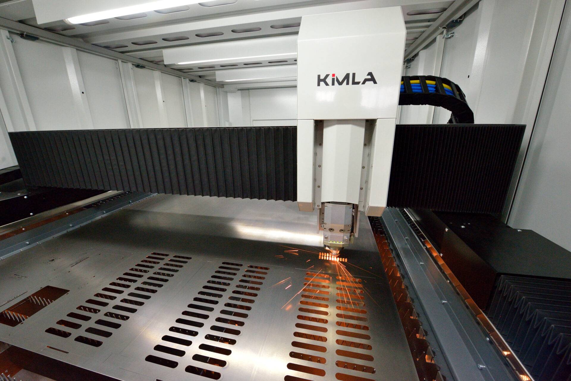
Frame design
Given the speed that fibre lasers are expected to operate, the frame design should be rigid, accurate and stable. Ideally, the laser body would be one solid piece, monolithic, machined in single process. The CNC millers required to machine entire frames in one go are very expensive, and not commonly found. For this reason, most manufacturers build frames in several pieces, usually two side walls connected by crossbars. For manufacturers outside of Europe this also allows them to be dismantled for shipping in containers.
However, if a machine frame is not monolithic, it will have compromised stiffness and be prone to twisting. To overcome this, manufacturers require a foundation for installation to provide the additional structural stiffness. Foundations are expensive, time consuming and limit the options for machine placement especially in rented premises.

Consistent with Kimla’s commitment to high standards, they invested in dedicated millers capable of machining entire monolithic bodies up to 3 m x 12 m in one process ensuring parallelism of 0.01 mm. Thanks to this, Kimla fibre lasers require no special foundation for installation.
Ergonomic working
Access to the working area on any machine is an important consideration. For most fibre lasers, doors are on the narrower side of the laser – this is the simplest (and cheapest) solution but limits the area an operator can reach. Some manufacturers offer access from the long side of the machine but operators need to reach through the folding covers before reaching the work piece causing potential damage. To overcome this some machines turn the gantry to operate along the short axis, but this makes the gantry long, reduces dynamics and efficiency. Regardless, none of the above options allow the operator full access to the entire working area.
The ergonomics of the laser were a top priority for Kimla in the design process. Their machines permit interlocked door access to all sides of the working area negating the need for an operator or technician to climb inside the machine. Everything is at your fingertips.
Traditional CNC Drives
All CNC machines have drives. They convert the control signals to mechanical movement across each axis. Usually these are servo drives operating on a rotational motor with an integrated encoder for measuring the drives position. The motor drives a mechanism converting the rotational movement into liner movement and thus linear movement along an axis. Usually, the mechanism for movement is a circulating ball screw, or, as is usually found in lasers, a toothed rack and pinion. These mechanical gears are subject to wear, backlash and ultimately inaccuracy or breakdown, especially when subjected to the fast movements of a fibre laser.
Vs Linear Drives
As you can probably tell by now, efficiency and speed are the underlying themes for an effective fibre lasers. A key part of this is acceleration, powering each axis to its set speed in the shortest distance possible. For this reason, manufacturers look to install larger and larger powered drives. The problem with this approach is that the larger the drive, the larger the mass that has to be accelerated which quickly becomes a self-restricting pursuit.
The answer is linear drives. While other manufacturers buy in linear drives from third party developers (often with technology 10-15 years old) Kimla are unique, manufacturing high power density drives in house. Through years of research, Kimla have developed drives with a three fold increase in power, without increasing the mass. This creates dynamics untouchable by any other laser manufacturer.
Working in a similar way to mag-lev trains, linear drives are a contactless drive system with movement induced through magnetic fields. With no mechanical or moving parts and inexhaustible power, the efficiency of a the drives is maximised. In a fibre laser, the cutting tool provides zero resistance during movement, so almost all the axis’ energy exerted during acceleration can be reclaimed during braking – a solution utilised by Kimla in the form of Common DC Bus technology. The reclaimed energy is then transferred to an accelerating axis. This recirculation of energy between drives minuses the overall consumption, increasing efficiency by up to 70%.
Kimla’s linear drives deliver another key characteristic, accuracy. The machine does not require referencing, as the positional reading is taken from a micro-barcode engraved on an invar tape along each axis with a resolution of just 1 nm. The result is unrivalled accuracy and zero backlash.
Where other manufacturers may state “linear drive technology” on promotional material for their machines, it often refers to just a single axis. Kimla fibre lasers feature linear drives on all three axes.
Control Systems
To understand the inherent restrictions most CNC systems place on a fibre lasers, we need to understand how they work. The diagram below shows the cutting path of a 90 degree angle at four different speeds. The faster the feed speed, the more of the corner is cut. Computer Numerical Control (CNC) was invented in the 1950’s to control servo speed on the basis of delay following an interpolators position. The interpolator provides positioning information, telling the control system where the cutting head should be at any given moment. The difference between the cutting heads actual position and the position set by the interpolator is known as position offset. After scaling, the offset value is as set speed for the servo’s driving head. What this means is that the greater the movement speed, the higher the position offset. Accurate cutting is achievable only if the machine is moving slowly. Fibre lasers are cable of cutting at extreme speeds, but when attempting this with traditional CNC controls manufacturers encountered precision issues up to a few millimetres.
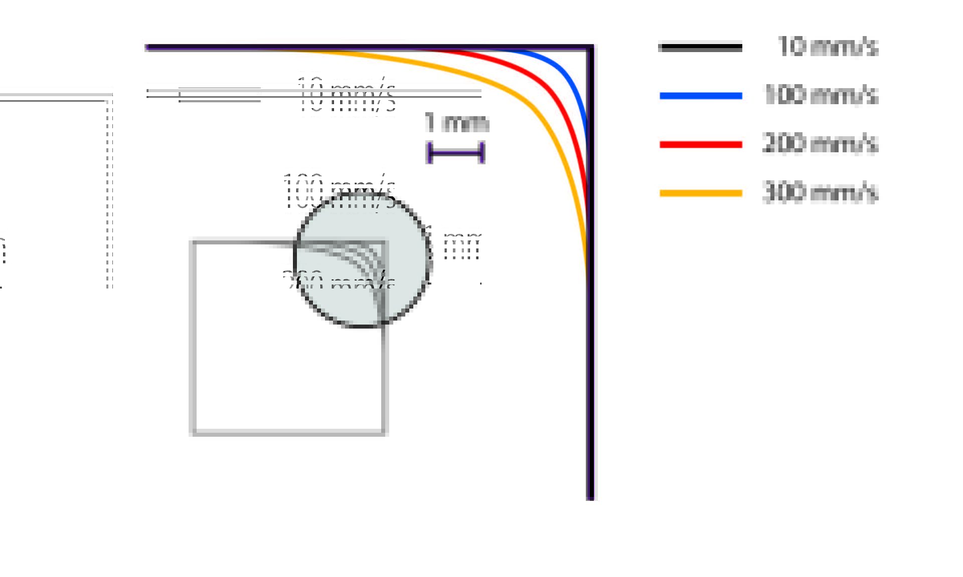
The only option was to reduce the machining speed in order to minimise the offset errors and maintain accuracy. This reduces the dynamics of the machine, and in turn reduces the efficiency.
Enter Kimla. In 1999, Kimla began work on a new type of CNC control, introducing a concept of offset-less control exploiting modern digital signal (DSP) processors. Previous technology had the interpolator set the position. With Kimla’s new solution the position, speed and acceleration are sent concurrently resulting in an off-set value of almost zero, regardless of the speed.
Another key factor is operating frequency. Old CNC controllers with scattered regulators operate at frequencies up to 2 kHz, allowing a servo’s position to be adjusted up to 2000 per second – fine for relatively slow machine tools, but for a fibre laser this is far for sufficient. For example, a cutting head moving at say 1000 mm/sec would be corrected just 2000 time over that distance, once every 0.5 mm. Modern fibre lasers can operate at over 4000 mm/sec which would be a correction every 2 mm.

To combat this, Kimla have regulators in the servo negating the need for slow bidirectional data exchange between the servo and interpolator. This allows Kimla to increase the adjustment frequency up to 20 kHz, in turn allowing for precise positional control at high speeds. Suddenly the fibre laser travelling at 4000 mm/sec is corrected every 0.2mm.
Hardware Vs Software Interpolator
A critical aspect to consider when evaluating machine control systems is the hardware foundation upon which they operate. Modern control systems typically rely on industrial PCs, greatly simplifying the development of user interfaces. However, only advanced professional control systems incorporate a dedicated hardware interpolator specifically designed to manage precise machine movements.
In contrast, some control systems function merely as software-based simulators running on standard PCs. Unfortunately, standard PCs are not true real-time systems since their processors must concurrently handle numerous tasks assigned by the operating system. Activities such as reading keyboard inputs, managing disk operations, rendering screen images, and handling network communications occur thousands of times per second. Embedded among these tasks are the algorithms that govern machine movements—calculating subsequent positions and transmitting commands to the servo systems.
Because these multiple processes compete for processing time, the intervals at which movement commands are sent to servos can vary, leading to timing inconsistencies known as ‘jitter’. Such jitter negatively affects the machine’s performance, causing vibrations, inaccuracies, and poor-quality edges on finished products.
To avoid these issues, professional-grade control systems feature a specialized hardware interpolator processor dedicated exclusively to controlling servo movements, ensuring consistent timing and optimal performance. While software-based simulator systems are significantly cheaper and can cost as little as one-tenth the price of hardware-based solutions, they sacrifice accuracy and quality.
Professional laser cutting machines should ideally be equipped with hardware interpolators; however, some manufacturers still adopt less expensive, software-based alternatives in pursuit of short-term cost reductions. Kimla, recognizing the critical importance of precision and reliability, has been manufacturing control systems with hardware interpolators for over 20 years, utilizing Real-Time Ethernet industrial communication protocols to maintain consistently high standards.
4. Programming, Software & Automation
G-Code
As Kimla pushed the boundaries of CNC technology, they identified another issue that need attention. The cutting head follows a tool path – the path is stored in the form of coordinates known as G-Code that the head reaches one by one. This is relatively basic and outdated method of positional recording. Shapes and curves are stored as a polygonal curve consisting of tens of thousands of short sections making up the shape.
For high speed fibre lasers these polygon sections are often too short for the system to process. As the CNC system struggles to read each command fast enough the machine will vibrate, accelerating and slowing unnecessarily causing further restrictions in the overall efficiency and cutting quality.
Kimla’s answer was Dynamic Vector Analysis (DVA). This patented technology continually calculates the centrifugal acceleration value for the tool path based on the shape being followed. This allows for more precise speed calculations as the system batch processes code for greater throughput.
Laser programming
As CNC technology evolved so did the practicalities of programming machines. At first machines incorporated a primitive keyboard to allow code to be directly input and then stored on perforated tape. The development of personal computers allowed the editing and writing of programs away from the machine, then transferring them on storage devices. However, the process of programming was remained tedious, requiring thousands of lines of code to be created.
In the 1980’s developers created software to automate cutting path generation. Countless iterations of CAM software become available as more and more companies entered the market each creating their own control systems. The issue of compatibility between CAM software and control systems quickly emerged hindered by the variety of machines and infinite configurations available. This led directly to the need for an additional piece of software to link CAM systems to controls systems – a postprocessor.
Postprocessor
To put it simply, a postprocessor translates tool path instructions from CAM software into language a CNC machine can understand. Postprocessors are often developed over time, created by the CAM software developer. Testing and correcting, the postprocessor is honed over time as the quality of code heavily influences the efficiency of the machines operation. The CAM provider doesn’t always understand the machines limitations, or fails to focus on smooth data exchange with the machine, or misses key functionality from the machine. In addition, if machine manufacturer changes supplier of CAM software operators of older machines many no long receive assistance or updates.
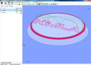
In order to solve this issue, Kimla designed and developed their own CAD/ CAM and nesting functions in one unique control system.
CAD/CAM/Nesting
Up till now lasers have been programmed by external CAM software. Developed over the past 20 years, Kimla’s CAD/ CAM/ Nesting system is truly pioneering. Through continual evaluation and customer feedback, functional innovations are added and refined making it one of the most powerful and intuitive control systems available. Keeping the design in house also allows Kimla to develop new machine features far quicker than any other manufacturer, further pushing the envelope of fibre laser technology.
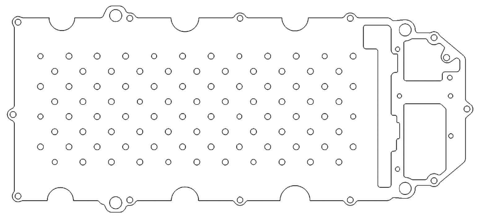
CAD – Computer Aided Design (CAD) is a vector graphics editor that facilitates the creation of drawings, shapes, designs etc in various file formats (.dwg, .geo, .taf, .hpgl etc). In addition to design functions, CAD software is vital for fibre lasers for automatic cleaning and closing of outlines.
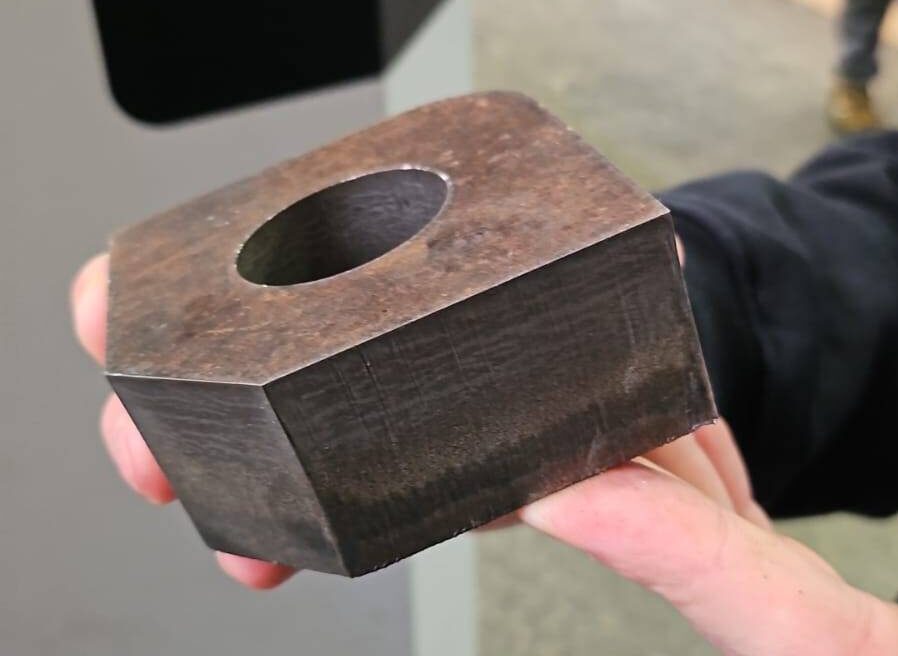
A fibre laser creates a gap when cutting, depending on the type and thickness of material this gap can be between 0.05 and 0.4 mm. If the laser followed the design outline perfectly it would result in parts being under or oversized. Therefore, the tool path must be offset by half of the gap’s width. The offset is dependent on the programmer knowing which offset correction is required – internal or external. The need for clearly defined “clean” drawings is essential, but this is not always the case.
If drawings are not correctly prepared, contours may not be closed, multiple lines can be on top of each other, overlapping etc. For a drawing created for human reference or printing this is not a problem, as there will be no discernible difference, but for a CNC machine this causes the programmer a headache to resolve.
To combat this, Kimla built a number of key functions into their software to automatically process drawings and correct errors. Closing open outlines, removal of overlapping lines and smoothing jagged contours are just some of the capabilities, leaving the drawing optimised for fibre laser processing.
CAM – Computer Aided Machining (CAM) takes the CAD information and turns drawing geometries into tool paths with all the commands for head movement, cutting speed etc. For fibre lasers manufacturers usually provide a ready made templates based on material type and thickness which then set laser power, punching and feed speeds etc. This is fine until something needs to be modified. Most laser manufacturers have cutting
parameters scattered throughout the control system. Any changes made by an operator may be accidentally left in place and subsequent processes then cut incorrectly or inefficiently.
Kimla consolidated all these machine functions into one easy to use system. The parameters are then stored within the cutting file so any future job can be executed with the given settings automatically. A huge time and hassle saving.
Common cut functionality is another fantastic feature of Kimla’s control system. When a fibre laser is processing multiple parts, straight line cuts can be nested against each other separated by the exact cutting width of the laser so only one pass is required to cut both sides. Depending on the components this can lead a dramatic increase in efficiency reducing waste and cutting time by up to 45%. Kimla’s nesting software creates common cuts automatically.
Nesting – The process of automatically arranging components within a working area to minimise material waste and optimise processing time. To achieve this the nesting program needs to know the shape and quantity of pieces to be cut, the angle of rotation permitted and material/ grain pattern. The computer algorithm then works out the nest orientation and positioning of the components to maximise the yield.

Depending on the order size, it is not always possible to utilise the full sheet leaving the sheet metal processor with two options; fill in the gaps with stock components, or store the half cut sheet for later use.
Kimla’s integrated nesting software allows the half cut sheet to be stored and reused later on. The nesting program knows which areas have been cut from and will reuse the available areas for new components next time round.
However, a powerful feature of the Kimla machines is that it allows a cutting process to be interrupted mid-way through the cycle, and introduce another component or set of components while taking into consideration parts already cut. This feature allows even more of the material to be utilised in the first instance.
Cutting reports – pre and post production
Accurate job costings are crucial for the success of any metal processing business. However, one the biggest challenges in generating project costs is the amount of machine time needed to complete the cutting process.
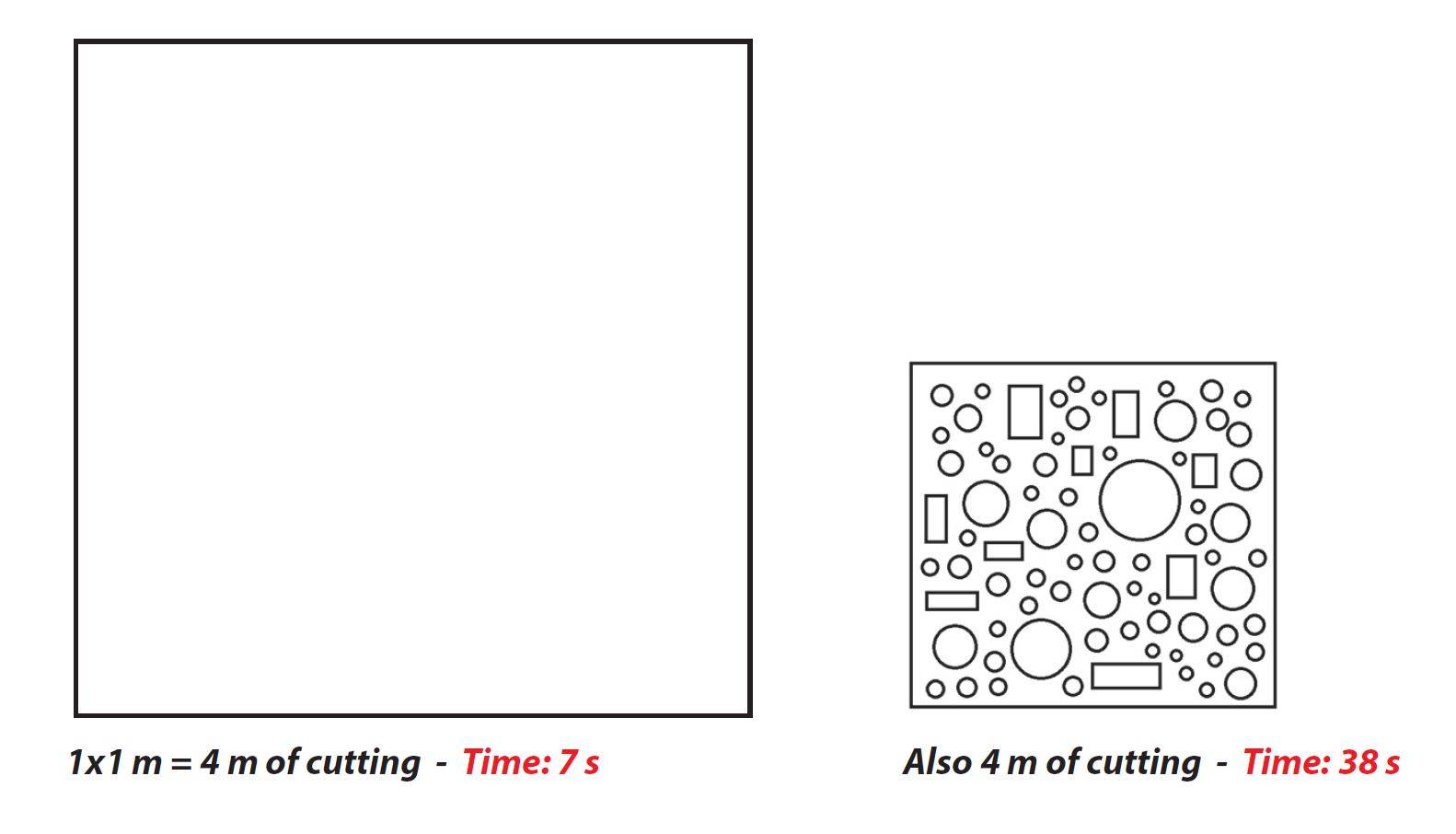
Take for example a simple square with 1 m sides. To produce this the machine must cut 4 m in total length. The time needed to do this, with say a 6 kW laser out of 1.5 mm sheet metal, would be around 7 seconds. But, if we take square with 400 mm sides but with a large number of apertures the total cutting distance is still 4 m but because of piercing time and machine dynamics the cutting time is around 38 seconds, over 5 times longer. Pricing these two jobs based on cutting distance alone will work out the same but with drastically different profit margins.
Of course it is possible to add additional charges for each piercing stage, and to some extent this will help make the costing more accurate but it is still very much an estimate. The only way to make an accurate costing…
Kimla’s integrated CAD/ CAM/ Nesting software allows for 100% accurate cutting time predictions as the control system is designed by the same company whop
As Kimla makes both the control system and physical machine, their projected cutting times are 100% accurate.
5. Buying the Right Machine
Checklist: Rules to follow when purchasing a fibre laser
Investing in a laser cutting machine is a significant decision, especially if it is the manufacturer’s first purchase of such equipment. Laser cutting systems represent some of the most substantial investments in CNC machinery, and making the wrong choice could seriously impact a business’s profitability and competitiveness.
Prospective buyers should begin by gaining a fundamental understanding of laser technology and its practical applications. Although this research can be time-consuming, it is crucial to prevent potentially costly mistakes.
Whenever gathering information, seek to obtain responses in writing (e.g., via email). Suppliers might use technical jargon to oversell their machines, and having written records provides clarity and a reference point for accountability.
Emails also help refresh memory and serve as documented assurances regarding machine specifications, ensuring suppliers deliver on their claims.
Laser cutting machines generally fall into two broad categories: those emphasizing reliability and those focusing primarily on higher performance. A reliable machine may not necessarily offer maximum performance, and high-performance machines might not always be reliable. Equipment from reputable brands typically offers consistent performance and reliability, though it may not always be the most cutting-edge option available.
It is important to note that larger companies often have significant overhead costs, which they may offset through after-sales services rather than increasing product prices. For instance, identical replacement components like safety windows can vary significantly in price due to patented designs or supplier exclusivity. Some suppliers also use proprietary software to restrict components, artificially inflating replacement costs.
Another aspect impacting long-term ownership costs is after-sales service. Before purchasing, it is crucial to confirm the prices of spare parts and maintenance services, as costs can vary widely between suppliers. Kimla, for example, prioritizes transparency by not profiting from after-sales technical services, charging only to cover service-related expenses, typically resulting in lower overall maintenance costs.
Large corporations often have slower product development cycles, sometimes taking up to a decade to bring new products to market. Consequently, their latest equipment may already lag behind current technological advancements at launch. Conversely, machines manufactured outside the EU may attract buyers with lower initial costs but often compromise quality, reliability, and long-term serviceability.
To effectively evaluate a laser cutting machine, buyers should consider asking suppliers these critical questions:
- Is the laser manufactured within the EU, and does the manufacturer provide local support?
- Is the laser source manufactured within the EU with available local support?
- Is the laser head manufactured within the EU, and is local service readily available?
- Is the control system EU-made, with local technical support?
- Has the supplied operated locally for at least ten years?
- Does the supplier maintain a laser showroom?
- Does the supplier have an available inventory of spare parts?
- Does the supplier have established customers owning multiple laser machines?
- Does the equipment carry an EU-issued Declaration of Conformity?
- Does the control system incorporate an equipment interpolator?
- Can the laser machine be installed without requiring foundational work?
- Does the machine have a fully enclosed housing with certified infrared filters?
- Is CAD/CAM software provided directly by the laser’s manufacturer?
- Do all axes feature magnetic linear drives?
Careful consideration of these points will significantly enhance the buyer’s ability to choose a laser cutting machine that best aligns with their operational needs, budget constraints, and long-term business objectives.
Safety considerations
Enclosure and Infrared Filters:
Ensure that the fibre laser is equipped with suitable housing and certified infrared filters. Operating lasers without these safety features is strictly prohibited in Europe.
CE Marking and Compliance:
Verify that the laser carries valid CE markings and confirm that the certification originates from a recognized European certification body. Absence of proper CE marking could indicate non-compliance with European safety regulations.
Importer’s Responsibilities:
Be aware that responsibility for obtaining CE certification typically rests with the importer. Often, importers may lack the expertise or resources required to independently achieve CE compliance. In these situations, certification should be arranged through an accredited notified body. Request comprehensive documentation of the risk assessment procedure performed by the certification body. Operating machinery without appropriate CE marking and compliance documentation is prohibited by law.
Warranty and Installation Considerations
Warranty Coverage:
Be aware that certain laser cutting system components have unpredictable lifespans and may not be covered by warranty. To avoid unexpected costs, request from your supplier a clear list of components excluded from the warranty, accompanied by an itemized price list. Ensure your purchase contract explicitly states that all parts not mentioned in the exclusion list are fully covered by the warranty.
Installation Requirements and Foundations:
Confirm in advance all installation prerequisites, particularly the conditions for foundations or flooring. Some fibre lasers require a specially prepared foundation, which may be problematic if you rent your facility and cannot modify the floor. (Note: Kimla fibre lasers do not require special foundation preparations.) It’s important to clarify this, as some suppliers may refuse warranty service if faults result from improper installation or lack of suitable foundations.
Additional Checks:
Consider also verifying the following points:
Recommended operating temperature range for the laser.
Safe storage temperature limits.
Machine’s resilience against sudden power outages or interruptions, and whether such incidents could cause damage.
Contract Specifications and Commissioning Considerations
Sheet Dimensions and Material Types: Ensure the purchase contract explicitly specifies the dimensions, material types, and thicknesses of metal sheets the laser will cut. Do not rely solely on general catalogue specifications, as exceptions or variations may apply. Be cautious of supplier offers containing disclaimers like: “All parameters indicated are for reference purposes only and are not guaranteed.” Always read and understand contracts thoroughly.
General Terms and Conditions: If no specific contract is provided, the purchase might proceed based on the supplier’s General Terms and Conditions of Sale. Review these terms carefully, retain copies, and consult legal advice if any provisions are unclear or ambiguous.
Commissioning and Training Validation: When commissioning the machine, confirm the laser’s capability to cut all specified types and thicknesses of metal sheets. Do not sign commissioning protocols until the laser operator can independently perform these tasks. This also serves as a practical evaluation of the training quality provided.
Software and Postprocessor: Clarify the software used for generating tool paths, identify who is responsible for creating and maintaining the postprocessor, and verify compatibility between the postprocessor and all laser functions. Misalignment here could lead to unexpected operational issues.
Software Updates and Corrections: Establish clear guidelines regarding responsibility for software updates, corrections, and modifications of both the software and postprocessor. Confirm how, by whom, and under what conditions updates will be provided.
Control System Verification: Inspect and confirm the details of the machine’s control system, including its name, model, and authenticity as a professional-grade system rather than merely a software simulator.
Documentation and Manuals: Verify that complete versions of operational and service manuals are provided with the machine.
Component Manufacturers: Request information about manufacturers of critical machine components, including servos, gears, linear guides, pressure regulators, motors, inverters, electromagnetic valves, and PLC units.
Control System Software Backup: Ensure the machine includes a copy of the control system software to facilitate repairs or replacements in case of damage. Without this software backup, repairs may become impossible.
Supplier’s Spare Parts Inventory: Physically inspect the supplier’s inventory of spare parts. Given the complexity of laser systems, prompt maintenance depends significantly on immediate availability of components.
Laser Efficiency Verification: Assess the machine’s actual cutting efficiency since performance varies significantly between machines. Provide the supplier with .dxf files containing sample components for cutting from various materials and thicknesses. Request returned samples with documented cutting times, and retain these as benchmarks during commissioning. Ideally, stipulate in the contract that these cutting times will be verified during commissioning.
Competitive Quotations and Cost Analysis: Obtain quotations from alternative suppliers or service providers for cutting similar samples. Separate quotations clearly into material and cutting costs. Using these quotations and cutting times, calculate potential hourly production and assess overall profitability and operational efficiency.
6. Conclusion
Making the Right Investment
Investing in a fibre laser cutting system is a critical business decision with long-term impacts on productivity, profitability, and operational flexibility. By carefully considering technical specifications, compliance requirements, warranty coverage, and supplier reliability, you’ll be well-positioned to make a confident choice.
Use the guidance and checklists provided in this guide to thoroughly assess your options, ensuring the machine you select aligns perfectly with your production needs and growth objectives. Remember, the right fiber laser not only delivers immediate performance improvements but will serve as a valuable asset for years to come.
For expert advice, demonstrations, or further information, feel free to contact our dedicated team—we’re here to support you every step of the way.
Tel: 0115 986 5201
email info@daltonswakin.com